Our pledge is to help the UK achieve a low-carbon future.
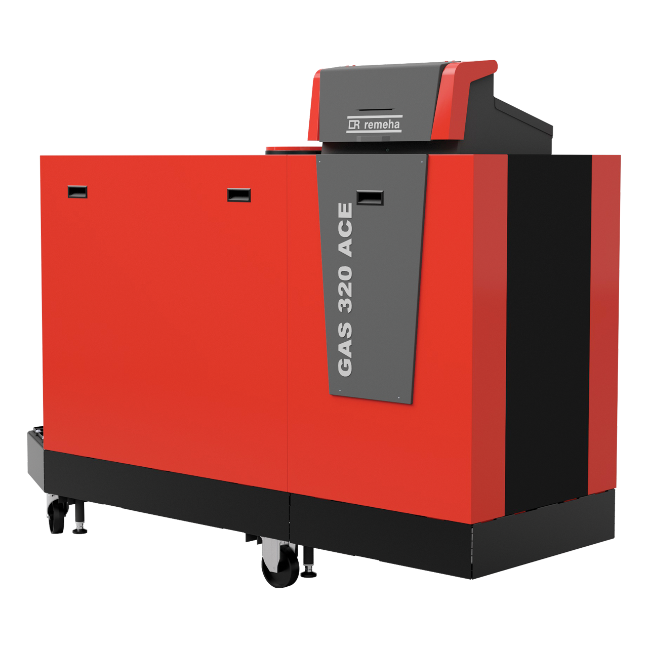
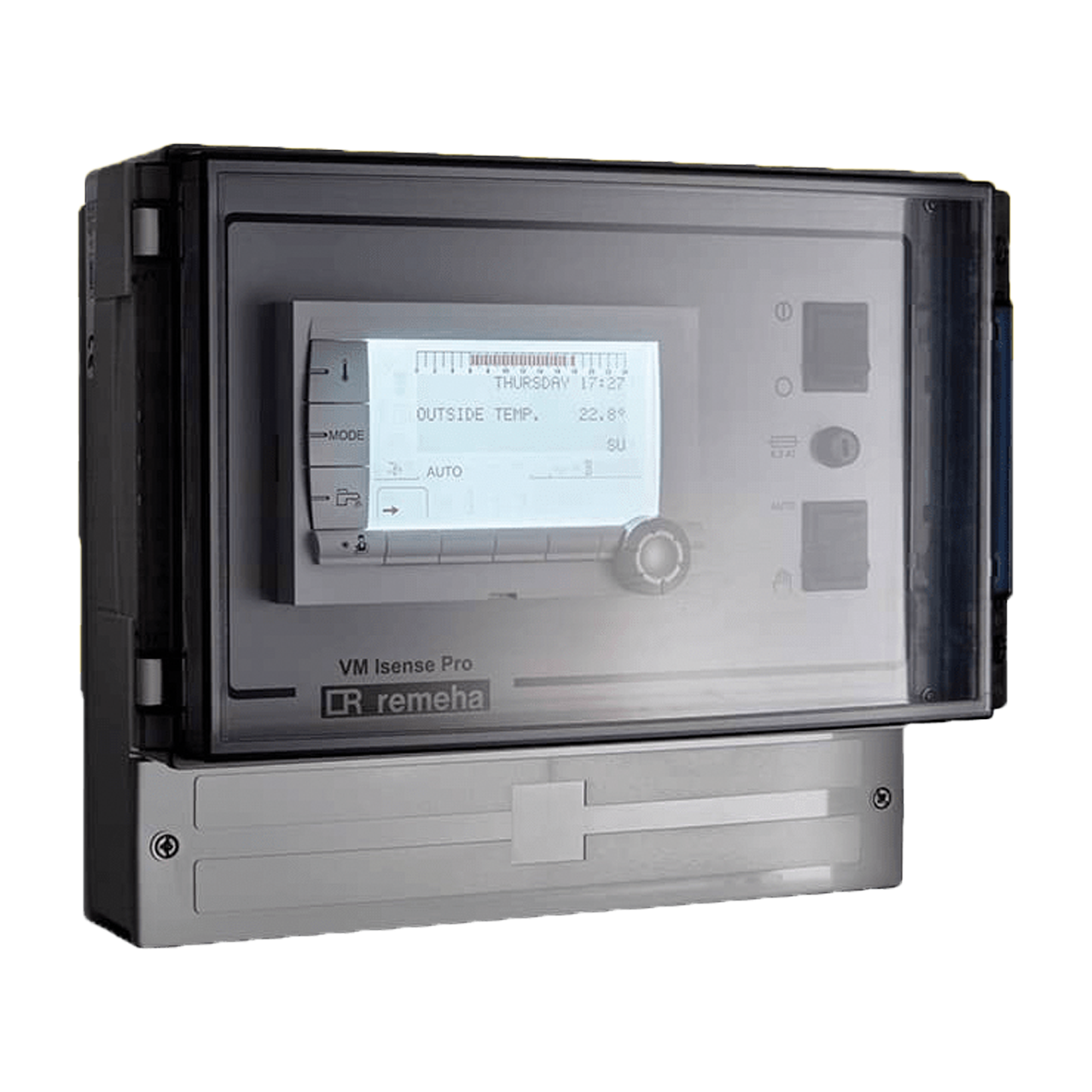
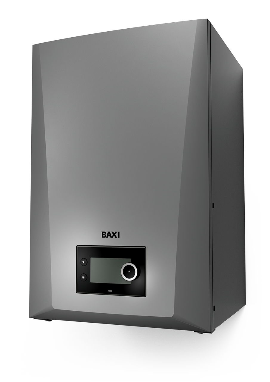
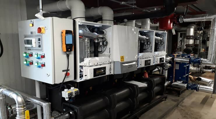
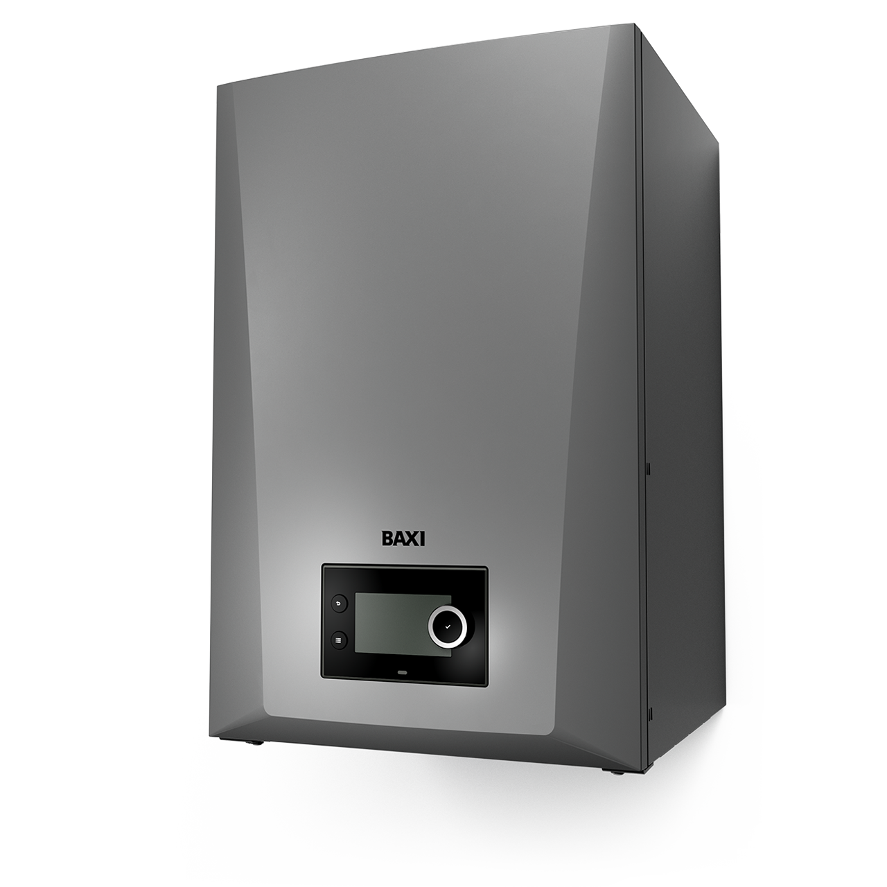
This runs through each product in this unique range of energy-efficient heating solutions. Each and every product is engineered to the highest quality for unrivalled performance and ease of installation.